Tuesday 27 March 2012

Editing Reference Surface for Pipe Network Structures

If you need to change or set the surface referenced by all the structures in your pipe network you can do this through the Toolspace.


On the Prospector Tab<Pipe Networks<Networks - expand the network you want to update. Highlight Structures - the list of structures will be displayed in the pane at the bottom of the toolspace. Highlight one of these and press CTRL A to select all. Scroll across until you come to the Reference Surface column. Right click on reference surface column header and select edit. You can then set or change the reference surface for all structures in the network. See screen grab below:


Monday 26 March 2012

Adding Custom Pipe Sizes

Depending on what pipe network catalog you are using you may or may not have access to your desired pipe size. For example if I am using the UKIE Part catalog < _Drainage Storm Water parts list and looking at the Concrete Pipes SI family. Adding all part sizes to the family I see that there is no 400mm dia pipe. Normally not a big deal here but apparently is commonly used in Bahrain!


You can easily define a new part size. Type PARTBUILDER at the command line. 


Double click on the part you wish to edit.
In the parametric building environment expand Size Parameters, right click on BdyD1 and select Edit.
In the Edit Part Sizes dialog box, click New to add a new size as shown below:
You can then add in part dimensions as necessary.

Friday 23 March 2012

Windfarm Access Roads - Earthworks

I have been working on a windfarm job recently where the earthworks for the access roads varied depending on whether the design was in cut or fill at a particular location.

In cut the earthworks needs to slope up to meet the existing ground at a 1:1 slope. In fill we needed to slope down to meet the underlying rock layer at a 1:1 slope first and then back up to existing ground at 1:1.

Typically the access road in cross section will slope towards the uphill side of the road and a ditch is placed on this side. See a previous post on a quick method for identifying the uphill side.

Typical road assembly minus earthworks might appear as follows:
For the drainage ditch I am using the Ditch subassembly.


The ConditionalCutFill subassembly will be used to control how the earthworks is applied depending on whether we are in cut or fill. This is located on the Conditional tab of your Tool Palettes.

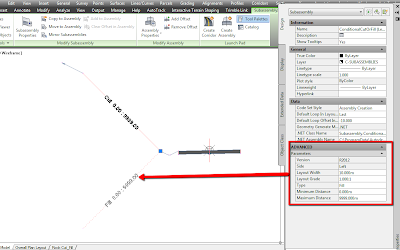
Looking at the cut situation first we will begin by applying a conditional cut subassembly to the back of the ditch:


The Layout Width and Layout Grade do not have any effect over the behaviour of the subassembly - they just control how the subassembly appears. I set my Type parameter in this case to Cut and leave the min and max values as they are. Attach this to the back of the ditch as shown above. In the cut situation I want to slope back up to the existing ground at 1:1. Use the LinkSlopeToSurface subassembly (Generic tab of Tool Palettes) and set the Add Link In parameter to Cut Only. Attach this to the end of the conditional cut subassembly as shown below:
Next apply another conditional subassembly to the back of the ditch - this time setting the Type parameter to Fill.

In the Fill situation we want to slope down to rock first at 1:1 - use the LinkSlopeToSurface subassembly again. Set the Add Link In parameter to Fill Only. Attach this to the end of the conditional fill subassembly.
From the rock layer we want to slope back up to existing ground at 1:1. Use LinkSlopeToSurface once more and set the Add Link In parameter to Cut only. Attach this to the end of the link to rock subasembly.

You can mirror all of the earthworks subassemblies to the other side of the assembly to speed things up. Just select the subassemblies you want to mirror and choose Mirror Subassemblies from the ribbon.

The complete assembly will look something like this:


When you are setting targets later in the corridor it is important that you have named each subassembly so that the name identifies what surface you will be targetting. e.g. Cut to Rock Left 1:1.


Create your corridor and set the targets in the corridor properties as required - see screen grab below for an example of how they might look.
Now we have our various earthworks conditions being controlled automatically by one assembly. Should changes be made to the vertical design of the roads later, the cut/fill conditions on the conditional subassemblies will look after any changes to the earthworks for us. See sample of what the resulting sections look like below: (existing ground - green; top of rock - magenta; road surface - red)

Cut Situation:

 Fill Situation (on right hand side):

If you are looking to explore the conditional cut and fill subassemblies a bit further I would recommend working through the example at the following link:


Thursday 22 March 2012

AutoCAD xref and scale

An old one but a useful one nonetheless. You have one drawing (we'll call it the source drawing) drawn to inches and the second drawing (destination drawing) which has been drawn to meters. You want to insert the source drawing into the destination drawing and have AutoCAD scale the inserted drawing for you.

You need to set the Insertion Scale units in each drawing so that AutoCAD knows what scale factor to apply when inserting.

First open the source drawing and type UNITS at the command line. Set the Insertion Scale units to inches. Close and save.

Next open the destination drawing and set the Insertion Scale units to meters. 


In the destination drawing type XR at the command line to start the xref command.
The source drawing will be inserted and scaled to meters.


Have you ever worked with two drawings that were drawn to the same units but appear at different locations/scales when one is inserted into the other? In these instances make sure that the insertion scale units are set the same in both drawings. Different insertion units is most likely the reason this is happening.

Friday 9 March 2012

Urban Overlay

I had a query this week about where you would start when designing an urban overlay in Civil 3D. The design involves planing out and replacement of existing surface with the requirement that we must tie back into existing road levels at the curbs. Desired road crossfall is 2.5% with flexibility to reduce this if required.


Start off by creating your existing ground surface - in my case creating from 3D polylines and AutoCAD blocks representing spot heights. Next create the existing road centreline alignment and profile. (Copy the 3D polyline for road centre and turn it into a 2D polyline - then create alignment from this). Also create existing pavement edge alignments and profiles in the same manner. This is what I have so far...


The subassembly that we are going to use is OverlayCrownBetweenEdges.
Like most subassemblies the layout appearance is not that important but rather the properties of the subassembly.
For a detailed explanation of the behaviour and properties of this subassembly see the help menu. In my case the offset values are going to be controlled by the existing pavement edges - these will be set as targets in the corridor later - and I can ignore the left and right offset properties. I want to achieve a min slope of 2.5% on my finished road surface. The subassembly will examine the existing road surface at each corridor sampling frequency and determine the higher of the control points (pavement edges). It will then apply the min slope from this point back to the centreline and then slope back down to the opposite pavement edge at whatever slope is necessary. Since this slope value will vary and depends on what the existing road surface is like at each sampling frequency you are best to set a relatively high max. slope value. If the slope needed is greater than the max. set in the properties then the corridor will not be created at this point.


I am leaving the crown height value to zero also - setting a value here can override min/max slope values. I want my design parameters based on the slope values only.


When creating the corridor use the existing centreline alignment and profile. In the target mapping dialog box select the alignments and profiles representing existing pavement edge to define the offset and elevation values for the road edges.
The resulting sections look like this...
You can see the result - the existing ground is higher on the LHS, C3D applies the min slope out from this point towards the Cl and then applies whatever slope is necessary to tie back to existing pavement edge. If the slope is too high on the lower side you can easily edit the subassembly properties to reduce the min slope value, or use the corridor cross section editor if you want to modify only a small region.

Friday 2 March 2012

Ulster Canal Visualisation

See link below to part of a visualisation of the Ulster Canal made for Waterways Ireland. More clips to follow...


Civil 3D modelling by Amicus Technology. Visualisation by Siscin.
If watching in full screen set the quality to the maximum...

The Ulster Canal – Upper Lough Erne to Clones is located in County Fermanagh, County Monaghan and County Cavan in Ireland and N. Ireland. From Upper Lough Erne to Clones the navigation begins at Quivvy Lough in County Fermanagh and then travels up the River Finn to Gortnacarrow, travelling along the County Cavan boundary at Castle Saunderson. From Gortnacarrow the canal travels north east to Clones, crossing the international border between Northern Ireland (County Fermanagh) and Ireland (County Monaghan) three times. The proposed navigation will be approximately 14km in total, with 5.5kms of river navigation from Quivvy Lough to Gortnacarrow and 8.5kms of canal from Gortnacarrow to a 36 birth marina at Clones. Over this section of canal there are 14 bridges that will have to be replaced, redesigned or restored.